Here is a little work in progress report on a gearbox I have been building recently.
Its nothing revolutionary (very similar to Petespeed, and the system on Metzy's carbon bike), but its simple, and easy to build in the home workshop with handtools (and a lathe).
Here is the xpost from farkin.net
Update 24/8/07
Photos have been a while, unfortunately. Photobucket was closed for maintenance.
Today I machined the bearing cups, tapped the threads, drilled the side plates and rough cut the inner plates. I haven't any pictures of that yet though, maybe tomorrow. I'm going to try and machine the thread on the collar to accept a BMX clutch tomorrow. I got a hold of some fresh aluminium bar stock, so I should be able to do a lot more machining in the upcoming weeks. I'll keep you posted.
Update 8/7/07
Hey guys,
just a bit of an update on the gearbox project. I have some of the more basic pieces machined now. Its taking a bloody long time, because I don't have access to the machines very often, or for very long at a time (meaning, consequently, that most of the time I do have is wasted on setting everything up).
The parts I've completed thus far
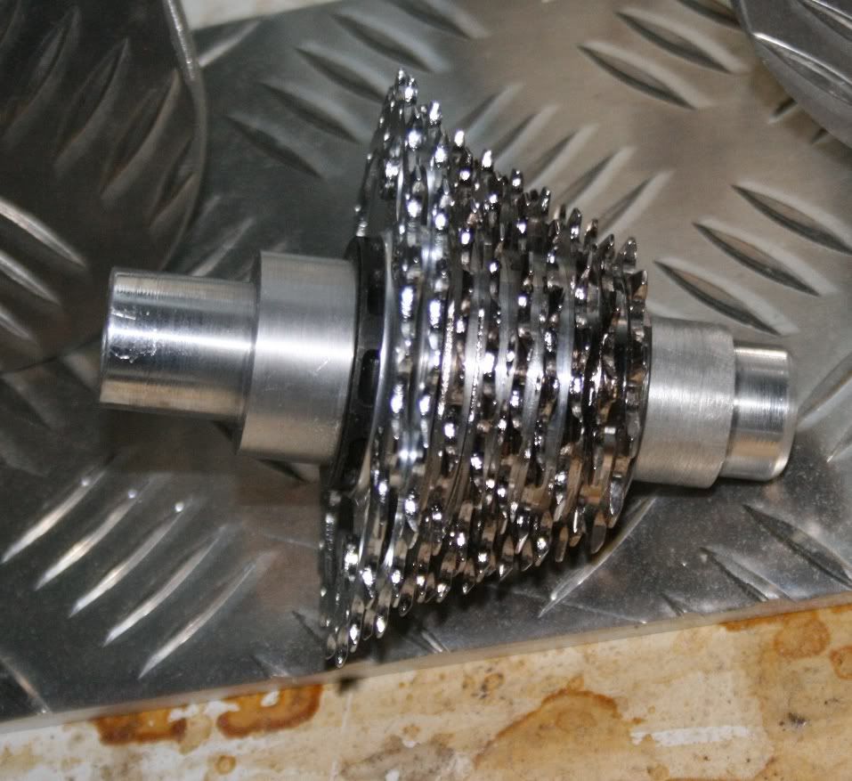
1. The top cog assembly. Basically an old shimano freehub body bored out, drilled, and then bolted (grubscrews) and loctited onto an aluminium spindle. I found it was a much simpler way of connecting the cassette to the spindle, rather than the alternative of replicating the cassette interface on the aluminium with a mill.

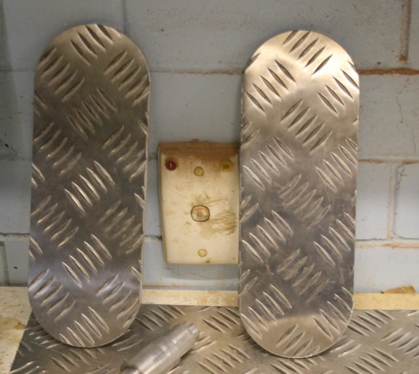
2. The outer plates - self explanatory. 5mm checker plate, because thats what I was given by some generous local companies. These plates will have two ~50mm holes at the centerpoint of those radius'. I'll bolt two toleranced 'bearing cups' on the outside face of those holes, so that the bearings won't twist or pop out.

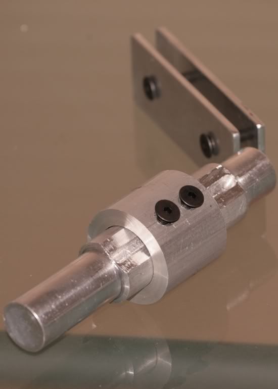
3. Bottom/drive spindle. Basically an aluminium spindle with a flat face, and a groove machine in that face. An outer collar floats on this spindle, maintaing positive drive with two bolts protruding through a 'key' which matches the flat face, and finally into the machined groove. A cog will obviously be attatched to this collar at a later stage. The purpose of allowing lateral float of the collar is to maintain a straight chainline.
Build Note This bottom spindle will now change, (no fiddly key, just two bolts in a trench) because frankly, this one is a POS. Tolerances are visibly loose and floppy. Picture shows roughly what will end up on the final prototype. I'm going to make two 'collars' also - one to carry BMX clutch (to shift without pedalling, while coasting) and one for a standard 22t ring (simpler, no shifiting advantage.

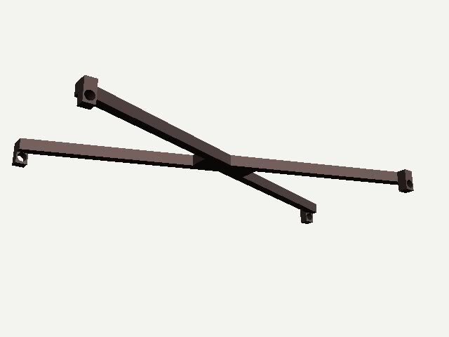
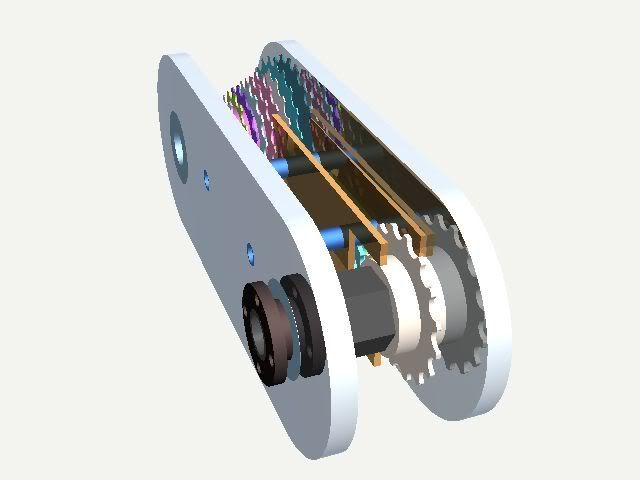
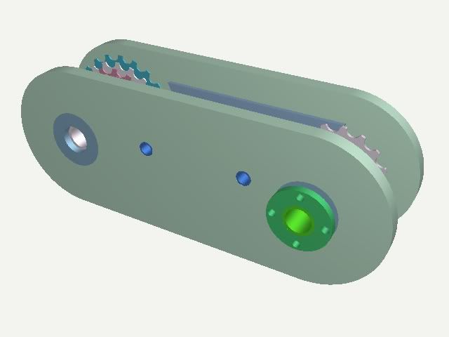
And finally, som CAD pictures of what it will look like (roughly, few exceptions) when its done.

Things that will change are:
Width - the finished model will be about half as wide as the CAD model suggests
The side plates will be reduced to 5mm width with bearing cups, rather than 10mm alloy (to save weight)
Those guide pins for the derailleur system will change position
The whole thing will have a sort of metal skin sealing everything with sump lubrication.
Update 4/5/07
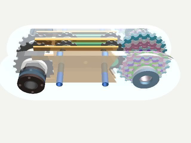
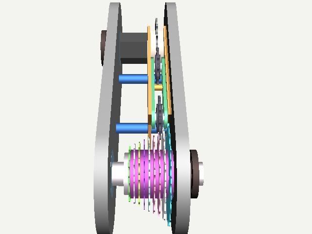
Some preliminary cad pictures of what I'm aiming for. (material renderings are just to show different parts, real project will not be made from wood and ceramics, as seen in the drawing)
Basically, the white shaft without a sprocket (will have a cassette on the threaded section for gear variance) is powered via a chain driven from the bottom sprocket, which slides along the hex shaft to maintain a straight chain line. Gear shifts are controlled by the center chain box, which houses two sprung jockey wheels to counter chain slack. The chainbox slides laterally on the two rails, its position is controlled by standard shifting cable+shifter.
Its nothing revolutionary (very similar to Petespeed, and the system on Metzy's carbon bike), but its simple, and easy to build in the home workshop with handtools (and a lathe).
Here is the xpost from farkin.net
Update 24/8/07
Photos have been a while, unfortunately. Photobucket was closed for maintenance.
Today I machined the bearing cups, tapped the threads, drilled the side plates and rough cut the inner plates. I haven't any pictures of that yet though, maybe tomorrow. I'm going to try and machine the thread on the collar to accept a BMX clutch tomorrow. I got a hold of some fresh aluminium bar stock, so I should be able to do a lot more machining in the upcoming weeks. I'll keep you posted.
Update 8/7/07
Hey guys,
just a bit of an update on the gearbox project. I have some of the more basic pieces machined now. Its taking a bloody long time, because I don't have access to the machines very often, or for very long at a time (meaning, consequently, that most of the time I do have is wasted on setting everything up).
The parts I've completed thus far
1. The top cog assembly. Basically an old shimano freehub body bored out, drilled, and then bolted (grubscrews) and loctited onto an aluminium spindle. I found it was a much simpler way of connecting the cassette to the spindle, rather than the alternative of replicating the cassette interface on the aluminium with a mill.
2. The outer plates - self explanatory. 5mm checker plate, because thats what I was given by some generous local companies. These plates will have two ~50mm holes at the centerpoint of those radius'. I'll bolt two toleranced 'bearing cups' on the outside face of those holes, so that the bearings won't twist or pop out.
3. Bottom/drive spindle. Basically an aluminium spindle with a flat face, and a groove machine in that face. An outer collar floats on this spindle, maintaing positive drive with two bolts protruding through a 'key' which matches the flat face, and finally into the machined groove. A cog will obviously be attatched to this collar at a later stage. The purpose of allowing lateral float of the collar is to maintain a straight chainline.
Build Note This bottom spindle will now change, (no fiddly key, just two bolts in a trench) because frankly, this one is a POS. Tolerances are visibly loose and floppy. Picture shows roughly what will end up on the final prototype. I'm going to make two 'collars' also - one to carry BMX clutch (to shift without pedalling, while coasting) and one for a standard 22t ring (simpler, no shifiting advantage.
And finally, som CAD pictures of what it will look like (roughly, few exceptions) when its done.
Things that will change are:
Width - the finished model will be about half as wide as the CAD model suggests
The side plates will be reduced to 5mm width with bearing cups, rather than 10mm alloy (to save weight)
Those guide pins for the derailleur system will change position
The whole thing will have a sort of metal skin sealing everything with sump lubrication.
Update 4/5/07
Some preliminary cad pictures of what I'm aiming for. (material renderings are just to show different parts, real project will not be made from wood and ceramics, as seen in the drawing)
Basically, the white shaft without a sprocket (will have a cassette on the threaded section for gear variance) is powered via a chain driven from the bottom sprocket, which slides along the hex shaft to maintain a straight chain line. Gear shifts are controlled by the center chain box, which houses two sprung jockey wheels to counter chain slack. The chainbox slides laterally on the two rails, its position is controlled by standard shifting cable+shifter.
Attachments
-
 67.4 KB Views: 820
 -
 83.8 KB Views: 695
 -
 37 KB Views: 726

 there might be a slim chance i have some drawings made up on computer programs. but you know