Quantcast

- - - need help with materials strength - - -

ÆX

Turbo Monkey
Sep 8, 2001
4,920
17
NM
if you would like to follow my progress i will be posting in the TEXAS
board over the next 2 months start to finish
.

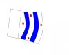
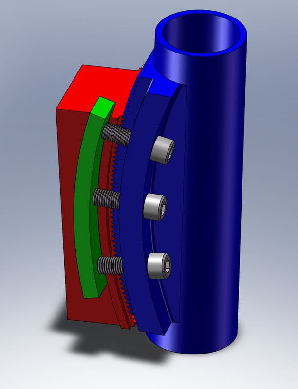
i am building my dh bike with a adjustable head angle.
here is how i though would be the best to do it with a
arced tovetail system. it pivots from right
above the front axle so as you go through the angles it keeps
the front wheel as close to parallel to the ground so you get
less bb height change. see gif.

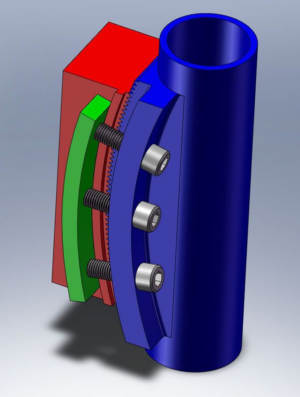
question is what kind of strength do i need my alum
head tube to have? its the male part. the female will
be molded carbon fiber. then two 8mm bolts to keep
it ats its angle. i should use 7076 i guess.

but what wall as compaired to the carbon do you think?

what about the amount of sholder area?

thanks alex


Boxxer

Monkey
Jul 18, 2005
856
2
Dirty South
Cool idea, but I'd be really worried about the integrity of that joint considering its location. I'm afraid if it were built sufficiently strong then it would probably weigh alot... and having a bunch of weight up high and out front on a bike doesn't sound like a good racing set up.

Maybe used on prototype frames to help set the desired HA for production bikes...
 

ÆX

Turbo Monkey
Sep 8, 2001
4,920
17
NM
i really think if it engineered there will be no problem and it will weight about 1/2 more that normal in that area. the whole frame
will be under 9 lbs.

people buy bikes based on geometry, if i have 5deg of head angle
adj it open my sales with less molds.

i would love to have ADJ head angle for lots of tracks.
 

Honus

Monkey
Jun 6, 2006
177
0
Boulder, CO
I just don't know about that.... it's definitely an interesting concept.
Are the 8mm bolts through bolts or are they threaded into each side?
The fit would have to be pretty precise for it to work- are you worried about the fit and/or the possibility of galvanic corrosion? Basically the only part that is supporting the head tube is the 30mm wide center section with a nice sharp corner.
Why not just have the outer sides of the head tube extend back and go around the central carbon part like a lap joint- I might have to do a drawing to show you what I mean- it would get rid of the stress raisers, be stronger and a lot easier to make while being functionally identical. And you could still use two 8mm through bolts to join it together, with specific holes for each head angle- that way it couldn't slip. You could also use a couple of thin walled aluminum inserts in the carbon part to eliminate the possibility of damaging the carbon when tightening the bolts.
 

Jonny5

Monkey
Feb 13, 2007
502
0
What about the commencal type of adjustable headtube? But make it bigger and three different inserts for 6 different angles?
 

_*sTiTcHeS*_

Monkey
Apr 24, 2006
386
0
yes, the post above mine is what i was going to suggest. sorry i dont know what exactly your asking but the commencal type is very hasle free and trustworthy. it deffinitly has more room to have 5deg. adjustment instead of +/- 1
 

alexchannell

Chimp
Jul 23, 2005
63
0
Post up solid models of your design instead of sketches, I do this kind of stuff every day at work, I should be able to help a bit.
 

ÆX

Turbo Monkey
Sep 8, 2001
4,920
17
NM
I
Are the 8mm bolts through bolts or are they threaded into each side?
yes they are thru with some large alum washers/locknuts
The fit would have to be pretty precise for it to work- are you worried about the fit and/or the possibility of galvanic corrosion?
no, galv i have never had trouble with, its more of a long term thing, bikes have a 5 year life generally. i would mold my carbon
off an exact headtube machined. so it would be hammer on tight.

Basically the only part that is supporting the head tube is the 30mm wide center section with a nice sharp corner.
i'll radius the corner, it is 4'' long 30mm wide. wouldn't that be stronger than the 1 1/8 hollow steertube? or the sides of the headtube that hold the headset?

Why not just have the outer sides of the head tube extend back and go around the central carbon part like a lap joint- I might have to do a drawing to show you what I mean- it would get rid of the stress raisers, be stronger and a lot easier to make while being functionally identical. And you could still use two 8mm through bolts to join it together, with specific holes for each head angle- that way it couldn't slip. You could also use a couple of thin walled aluminum inserts in the carbon part to eliminate the possibility of damaging the carbon when tightening the bolts
i thought of that too but have no idea how you could machine the headtube inside a chanel radiused. this seemed ot be the only way.
though i would rather have has the carbon in the middle and alum out
so i could have threaded the bolts in.
 

ÆX

Turbo Monkey
Sep 8, 2001
4,920
17
NM
What about the commencal type of adjustable headtube? But make it bigger and three different inserts for 6 different angles?
so they are inserts that are machined off center.

i don't like that as much b/c it changes your bb height too by 1/2'' per deg. my system doesn't.
 

Kornphlake

Turbo Monkey
Oct 8, 2002
2,632
1
Portland, OR
Add an additional profile to the sketch you revolved for cutting the slots and it will curve the back side of the base extrusion as well. You might have to modify the sketch for the base extrusion to add a little more material to the back side of the part so you can round it off.

Does that make sense? I tried to draw the sketch I'd use for the revolve feature, I'm not sure if you'll understand what it's supposed to mean though. I tend to think a little abstract sometimes.

My biggest concer is how stiff will the joint be laterally? I don't know how much material you are planning on using on the frame piece, it seems like you'd want to wrap as much material around the head tube as you can, maybe add a second dovetail concentric with the first and a pair of bolt holes aligned horizontally as well as the holes vertically so that you have a more ridgid interface with a little more overlap.
 

Attachments

ÆX

Turbo Monkey
Sep 8, 2001
4,920
17
NM
Add an additional profile to the sketch you revolved for cutting the slots and it will curve the back side of the base extrusion as well. You might have to modify the sketch for the base extrusion to add a little more material to the back side of the part so you can round it off.

Does that make sense? I tried to draw the sketch I'd use for the revolve feature, I'm not sure if you'll understand what it's supposed to mean though. I tend to think a little abstract sometimes.

My biggest concer is how stiff will the joint be laterally? I don't know how much material you are planning on using on the frame piece, it seems like you'd want to wrap as much material around the head tube as you can, maybe add a second dovetail concentric with the first and a pair of bolt holes aligned horizontally as well as the holes vertically so that you have a more ridgid interface with a little more overlap.
thanks that helped.
i think that the sholder might need to be thicker., its just as important as the center thivkness and should match it right?

center is at 20mm so the sholders should be 10mm each huh? ans 10mm of carbon on the outsides. i need to keep it all 60mm wide.
 

Kornphlake

Turbo Monkey
Oct 8, 2002
2,632
1
Portland, OR
I'm not real good with structural engineering type questions, and I don't know anything about designing with carbon fiber, my gut feeling is that it will work great with a little more overlap.

I tried drawing what I'm thinking of, the blue part is the dovetails. I'd put in two of them to really lock everything together. The red circles are bolt holes, I'd use horizontal and vertical holes, but that may mean removing too much material when you make the slots that allow the head tube to be adjusted.

You've got a neat idea, I'm not sure how valuble it is to anybody to have a BB height that doesn't change with the headangle, but I'm sure you could use it as a marketing feature.
 

Attachments

Biscuit

Turbo Monkey
Feb 12, 2003
1,768
1
Pleasant Hill, CA
thanks that helped.
i think that the sholder might need to be thicker., its just as important as the center thivkness and should match it right?

center is at 20mm so the sholders should be 10mm each huh? ans 10mm of carbon on the outsides. i need to keep it all 60mm wide.
Neat! That's a pretty cool idea, just be sure to overbuild it. An innovation that fails once will have an insurmountable uphill battle.

I agree, the shoulders should be thicker, if you could curve them, and match that in your carbon mold to distribute part of the load through the center of the dovetail (so not so much is held by the shoulders). I imagine quality controll and manufacturing on that is going to be extremely difficult.

If you haven't seen it before, check out this, it's got some neat info:
http://materials.npl.co.uk/NewIOP/DBFrameSet.html

It's got data for various materials, and outlines a few principals that a bike designer aught to understand (from what I've seen you already do for the most part).

I'm also a bit uncertain about how you would lock the two pieces together in an adjustable format. Too many holes and you lose a lot of strength.
 

ÆX

Turbo Monkey
Sep 8, 2001
4,920
17
NM
what about doing an insert like the commencels but not round but arced from the pivot i like above the front axle.
carbon around it, i like wrapping an object in carbon fibers work
better when encasing something.
 

Biscuit

Turbo Monkey
Feb 12, 2003
1,768
1
Pleasant Hill, CA
what about doing an insert like the commencels but not round but arced from the pivot i like above the front axle.
carbon around it, i like wrapping an object in carbon fibers work
better when encasing something.
You know, when you arc the headtube around a point like that, the bb height isn't changing but the bar height is. Not by much, but that should be considered. I think I would prefer the bb height changing instead of the cockpit layout. The added complexity may not be worth it.

Although by looking at your gif, it doesn't look like the bar height would change by much. You might want to find a compromise arc in your final design.
 

Biscuit

Turbo Monkey
Feb 12, 2003
1,768
1
Pleasant Hill, CA
what about doing an insert like the commencels but not round but arced from the pivot i like above the front axle.
I just had an idea.. or maybee just got what you were saying.

Have you seen the special ed adjustable stems?
http://www.specialized.com/bc/SBCEqProduct.jsp?spid=25255

They have a neat sleeve insert that is essentially a cylinder with a bored hole that is at an angle. You could create a few head tube inserts similar to this that had different stack heights at the bottom to adjust for fork height changes.

You could even make it an oblong piece that was integrated into the frame to give the top-tube adjustment you want.

To save additional costs the pieces could be flip-flop-able. So the one that was -5deg and added stack height to the bottom, could be flipped to be +5deg and reduce stack height.
 

ÆX

Turbo Monkey
Sep 8, 2001
4,920
17
NM
I just had an idea.. or maybee just got what you were saying.

Have you seen the special ed adjustable stems?
http://www.specialized.com/bc/SBCEqProduct.jsp?spid=25255

They have a neat sleeve insert that is essentially a cylinder with a bored hole that is at an angle. You could create a few head tube inserts similar to this that had different stack heights at the bottom to adjust for fork height changes.

You could even make it an oblong piece that was integrated into the frame to give the top-tube adjustment you want.

To save additional costs the pieces could be flip-flop-able. So the one that was -5deg and added stack height to the bottom, could be flipped to be +5deg and reduce stack height.
thats cool but i don't want it to pivot from anywhere near the center of the head tube.

bar height from 67 - 63 would change 21mm about straight down.
that can be solved with stem spacers easy if you wanted.

as you know you can solve bb heigth with fork legs and rear shock mounts but that changes bar height.

here is an insert that would go into a rectangular carbon head tube.


my bike is using a bmx chain from the bb to the high pivot, the bb will
be in a verticle slided with 1'' of adjustment also. but i don't want to
loose its full range of adjustment when i change headangles


DHRracer

Monkey
Sep 29, 2004
371
0
i really think if it engineered there will be no problem and it will weight about 1/2 more that normal in that area. the whole frame
will be under 9 lbs.

people buy bikes based on geometry, if i have 5deg of head angle
adj it open my sales with less molds.

i would love to have ADJ head angle for lots of tracks.
% 5 degrees of adjustment is huge/way to much.Make it more like +/-1deg for a total difference of 2deg.How much have you considered about trail(that little talked about geometry that is a result of head angle and fork offset)
 

Biscuit

Turbo Monkey
Feb 12, 2003
1,768
1
Pleasant Hill, CA
thats cool but i don't want it to pivot from anywhere near the center of the head tube.
I'm saying your inserts could be oriented, combining the angle and "stack height" (having a thick part at the bottom) so the angle and actual fork position would rotate as if it were pivoting around a point over the front wheel.

Stop your .gif at any point in that movement and you can clearly define bottom and top of headtube. Why not just create pieces that mimic that?

A slacker angled insert would have a higher stack height at the base, effectively making the axle to headtube/crown/bar length longer. Which would keep your bb the same.

as you know you can solve bb heigth with fork legs and rear shock mounts but that changes bar height.
Your right, that hadn't occurred to me.

here is an insert that would go into a rectangular carbon head tube.
That is way different than what I envisioned. It could totally work too. Tricky part would be ensuring it doesn't move or creak. But I think it's much more practical and manufacturable.


How much have you considered about trail(that little talked about geometry that is a result of head angle and fork offset)
If he's building it to be 29er compatible, trail is really important, which is why he would need more adjustment.
 

Biscuit

Turbo Monkey
Feb 12, 2003
1,768
1
Pleasant Hill, CA
my bike is using a bmx chain from the bb to the high pivot, the bb will
be in a verticle slided with 1'' of adjustment also. but i don't want to
loose its full range of adjustment when i change headangles
This is a tricky bike your planning!

If you can get all this stuff to work at a reasonable price point, I can't think of a reason why your bike wouldn't be a serious contender in any frame buying decision. (marketing aside)
 

ÆX

Turbo Monkey
Sep 8, 2001
4,920
17
NM
% 5 degrees of adjustment is huge/way to much.Make it more like +/-1deg for a total difference of 2deg.How much have you considered about trail(that little talked about geometry that is a result of head angle and fork offset)
here are some trail numbers. any slack dh bike is going to have long trail, its what we want too let loose.
26x2.5 is 27'' tall
boxxer fork rake is 42mm, 888 is 43.5, fox 40 is 44 so i averaged.
my 29 fork offest would have to be 2.125 to have the same trail numbers as 43x27''

HA---43mm 27''------43mm 29er-----my WB is 31mm!! 29er.

63---5-----------------5.5--------------6
64---4.7---------------5.2--------------5.7
65---4.4---------------4.9--------------5.4
66---4.1---------------4.6--------------5.1
67---3.9---------------4.3--------------4.8
 

alexchannell

Chimp
Jul 23, 2005
63
0
Here is my initial idea...still needs a few things but its pretty much there.
Works similarly to the locking mechanism on single bolt seatposts.


Btw, how did that 5th element model work out for you?
 

Honus

Monkey
Jun 6, 2006
177
0
Boulder, CO
Here's a quick sketch of what I was talking about- please forgive the crude nature of my drawing- it's late. Some of the proportions are a bit off but I think you get the general idea.
 

ÆX

Turbo Monkey
Sep 8, 2001
4,920
17
NM
Here's a quick sketch of what I was talking about- please forgive the crude nature of my drawing- it's late. Some of the proportions are a bit off but I think you get the general idea.
]
that is how i had it initially done but all the load sheers on the bolts.
might have to have like 4 8mm in there.
 

ÆX

Turbo Monkey
Sep 8, 2001
4,920
17
NM
Here is my initial idea...still needs a few things but its pretty much there.
Works similarly to the locking mechanism on single bolt seatposts.


Btw, how did that 5th element model work out for you?
i like the concept but it still puts the bolts holding your life.
i want to be able to use material strength/thickness something,
i can overbuild, to provide the strength.

i couldn't open the 5th shock. i have 2006...........?

thanks for your guys input, i need someone to bounce ideas off of.
 

Honus

Monkey
Jun 6, 2006
177
0
Boulder, CO
that is how i had it initially done but all the load sheers on the bolts.
might have to have like 4 8mm in there.
That's one of the reasons I like through bolts-as long as the bolts aren't loaded in single shear you'll be just fine. Also helps keeps them from coming loose....

For structural metals, the ultimate shear strength is about 60% of the ultimate tensile strength. Most "AN" grade shoulder bolts have a minumum tensile strength of 125,000psi. and would work well in this application. Don't use SAE grade 8 bolts- they aren't really appropriate for loading in shear. With the right bolts, the surrounding material will probably fail long before the bolts do. Just make sure the shoulder of the bolt goes all the way through. If you really want to be anal about it, you can get a bolt that is drilled for a castle locknut at the end so you can safety wire it.
 

alexchannell

Chimp
Jul 23, 2005
63
0
I wouldn't worry about bolt strength. For example, look at the bolt on the lower mointing point of an M1, it's about 3/16".
I agree about using inter part support though. I like the design your using, however to lock it in place better (right now your machining tolerances would have to be dead-nuts accurate) using a v-grove would work well. As you tighten the bolts, the v locks in and prevents any type of movement.

When you get a design you like, shoot me an email and I'll FEA it.

Yeah the shock is 2007. I can save it to iges or something but then you loose a lot of info.
 

ÆX

Turbo Monkey
Sep 8, 2001
4,920
17
NM
I wouldn't worry about bolt strength. For example, look at the bolt on the lower mointing point of an M1, it's about 3/16".
I agree about using inter part support though. I like the design your using, however to lock it in place better (right now your machining tolerances would have to be dead-nuts accurate) using a v-grove would work well. As you tighten the bolts, the v locks in and prevents any type of movement.

When you get a design you like, shoot me an email and I'll FEA it.

Yeah the shock is 2007. I can save it to iges or something but then you loose a lot of info.
i found a 90deg 3/4 drill point end mill, so i modeled around that.

i dropped one deg of adj for more material room. so its 66-65-64-63

this is looking good IMO.


www.bcdracing.com/psycho-billy-cadillac/mar/headkeyv.SLDPRT
 

alexchannell

Chimp
Jul 23, 2005
63
0
I'm liking the overall design.
Here is what I notice:

The model isn't to scale right now (the inner head tube diameter is almost 2") (FEA won't be accurate at all if not to the proper scale)

Those holes will be chalenging to hold a drill in (it will want to walk into the pocket next to it). You can do offset series of holes in both parts to gain a lot of strength and make the manufacturing easier.

...have to get back to work....
 

ÆX

Turbo Monkey
Sep 8, 2001
4,920
17
NM
I'm liking the overall design.
Here is what I notice:

The model isn't to scale right now (the inner head tube diameter is almost 2") (FEA won't be accurate at all if not to the proper scale)

Those holes will be chalenging to hold a drill in (it will want to walk into the pocket next to it). You can do offset series of holes in both parts to gain a lot of strength and make the manufacturing easier.

...have to get back to work....
even drilling the holes with an end mill they will walk?
might be able to space them out.

yes, its to scale, 1.5 headset and E13 adapters are about 2''.
bolt holes are 8mm.
 

Westy

the teste
Nov 22, 2002
54,512
20,312
Sleazattle
even drilling the holes with an end mill they will walk?
might be able to space them out.

yes, its to scale, 1.5 headset and E13 adapters are about 2''.
bolt holes are 8mm.

Use the shortest drill/mill you can find and drill pilot holes small enough that they will not touch. You can easily test on a piece of scrap to see if they drift on you..
 

alexchannell

Chimp
Jul 23, 2005
63
0
even drilling the holes with an end mill they will walk?
might be able to space them out.

yes, its to scale, 1.5 headset and E13 adapters are about 2''.
bolt holes are 8mm.
Chances of them walking with an flat end mill and slow feed are quite low. (no point is spot drilling for an end mill either).

The thing I see with the bolt hols going together, look at the very small amount of aluminum the bolt has to blow out. (mainly when landing hard and the bolt is in any position except the bottom ones).

I just checked the inner diameter of the headtube, it's 1.95". Unless I'm mistaken, that should be 1.5" and the E13 cups press into that and allow the usage of 1.125" bearings?
 

Kornphlake

Turbo Monkey
Oct 8, 2002
2,632
1
Portland, OR
You're mistaken, the steerer tube is 1.5, you'll need to add some clearance for a 1.5 headtube.

I'm not liking the idea of having one notch in the insert, vee shaped or dove-tailed. Think of it this way, you have a pivot at the bolt hole location in the lateral direction, the lever acting on the frame is as long as the distance from the center of the bolt holes to the center of the headtube, the lever reacting is as long as the distance from the center of the bolt hole to the back of the insert. If you can I'd add a little more length to the insert on the back side and another pair of bolts so that you don't have as much leverage on the headtube side and more on the frame side.

Like I said before I'm not a real good structural engineer and I don't know much about carbon fiber but I can see the interface on the frame side wanting to spread out behind the bolt holes where the edge of the headtube insert is pushing on it with a lateral load. With some dust, dirt and mud it will start wearing away at whatever is softer of the two, aluminum or carbon fiber.
 

ÆX

Turbo Monkey
Sep 8, 2001
4,920
17
NM
Chances of them walking with an flat end mill and slow feed are quite low. (no point is spot drilling for an end mill either).

The thing I see with the bolt hols going together, look at the very small amount of aluminum the bolt has to blow out. (mainly when landing hard and the bolt is in any position except the bottom ones).

I just checked the inner diameter of the headtube, it's 1.95". Unless I'm mistaken, that should be 1.5" and the E13 cups press into that and allow the usage of 1.125" bearings?
no, i have it right, its 1.95. the od of a 1.5 fork steerer is 1.5.

Kornphlake - Like I said before I'm not a real good structural engineer and I don't know much about carbon fiber but I can see the interface on the frame side wanting to spread out behind the bolt holes where the edge of the headtube insert is pushing on it with a lateral load. With some dust, dirt and mud it will start wearing away at whatever is softer of the two, aluminum or carbon fiber.
yeah, it would do that but the rigidity of the carbon wouls take 3/4 of the load from the bolt i am guessing.
its going to fit tight like hammer in, then bolts to tighten the wedhe to no slop.

the backside needs a radius so there is not a sharp corner next to the
carbon.