Quantcast

angled headtube reducers info/help

davep

Turbo Monkey
Jan 7, 2005
3,276
0
seattle
Ok, I have been toying with the idea of having some angled 1.5 to integrated standard reducers made to reduce or increase 1 degree of headangle. I am pretty confident that I could get some made that will do what I want and be applicable to a smll range of headtube lengths (+- 0.5") due to the ACB and crown race shape. THey would consist of two identical parts (top and bottom), rather than the single unit that another Monkey made.

I have a few questions that I was hoping some one might be able to help with

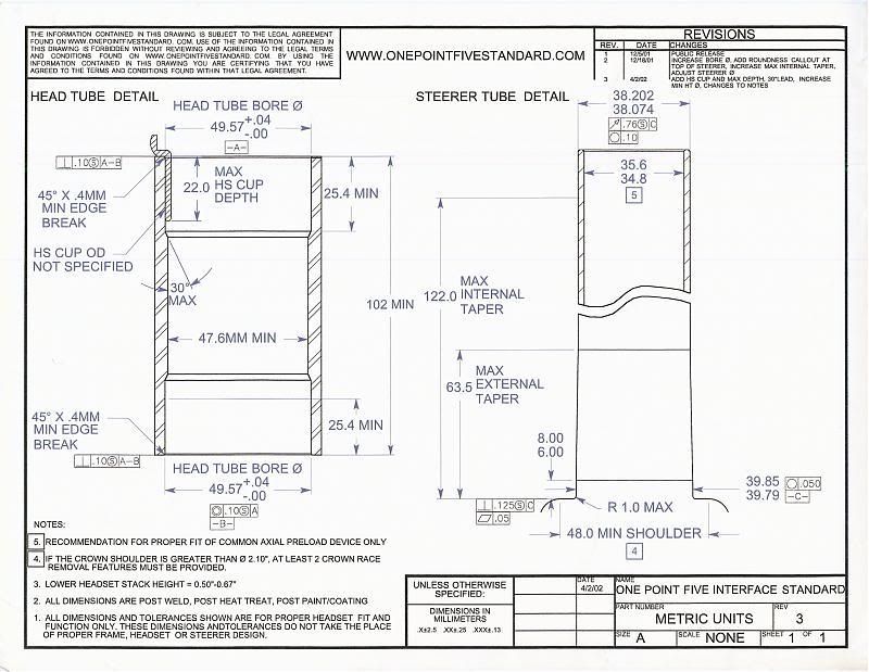
1) I canont find the 1.5 standard tech drawings any more. Does anyone know any specific measurements and tollerances for the bearing seat and external diameter. ( I can mic a part that I have, but I would need to remove from the frame and then remove the bearing). BYO, I know you made some non-angled versions at one time.

2) I have roughly drawn the part in Autodesk as I have it on my laptop...but I could most likely get acces to SW. Will the modeling software matter to the machinist? Do I need to get this into some CNC code, or is something that the machinist will/can do from the SW or autodesk files (sorry, EE not ME)?

3) Any rough idea how many of these I would need to get made to get a reasonable price? Zenkgarage..BYO??? 10? 100?


Any other info/data anyone wants to share? DW, I know you had some of these made....


Thanks
 

ohio

The Fresno Kid
Nov 26, 2001
6,649
24
SF, CA
2) I have roughly drawn the part in Autodesk as I have it on my laptop...but I could most likely get acces to SW. Will the modeling software matter to the machinist? Do I need to get this into some CNC code, or is something that the machinist will/can do from the SW or autodesk files (sorry, EE not ME)?
I can only help with this one, but generally any local machinists will want dimensioned drawings (which you create in Autodesk) and will figure out how to program the CNC themselves from that. If they're a pretty up to date shop, they may be willing to accept the autodesk files, but you'll have to have the drawings to get bids regardless.
 

davep

Turbo Monkey
Jan 7, 2005
3,276
0
seattle
I can only help with this one, but generally any local machinists will want dimensioned drawings (which you create in Autodesk) and will figure out how to program the CNC themselves from that. If they're a pretty up to date shop, they may be willing to accept the autodesk files, but you'll have to have the drawings to get bids regardless.
Thanks. No problemo with the drawings, I can do that easily.
 

davep

Turbo Monkey
Jan 7, 2005
3,276
0
seattle
You'll also want to be closer than +- .500 for head tube length. being .500 off would kill your headset.
Ideally yes, for sure, but I dont think in reality it will matter much. The bearings will be offset in the cups by only one degree. The change in that angle with a change in head tube length of 1/4" at either end will be pretty small (I will figure out what it is shortly).

Someone else here made a single cup offeset by a degree....and used an e-13 for the other cup. He claimed that it was holding up perfectly even with the bearings being off by a full degree.

The key in allowing this big tollerance is the angular contact bearing (no way it would work with a single row cartrage). and the conical crown race interface. These designs were used in a headset specifically to allow some angular variation between bearing planes...
 

davep

Turbo Monkey
Jan 7, 2005
3,276
0
seattle
I can help out with number one.
I'd be interested in a pair too - for a Sunday.
Thanks!! I remember there being an offical 1.5 web site, but what I thought was the address (onepointfive.org)now goes to a Chinese church.....
 

WBC

Monkey
Aug 8, 2003
578
1
PNW
Might be a good call to put up a thread to gauge demand. If the cups are under $100 retail, I know dozens of people that would snap those up.
 

bikerpunk98199

Turbo Monkey
Apr 24, 2005
1,313
0
the hood
Might be a good call to put up a thread to gauge demand. If the cups are under $100 retail, I know dozens of people that would snap those up.
I know a couple of people that would be interested as well as my self!

Keep us posted on how this turns out!
 

Sam B

Monkey
Nov 25, 2001
280
0
Cascadia
For the bearing contact dimensions... dig around on FSA's website (or call/e-mail them) for the "Headset Book" PDF. Both the common Orbit Z1.5R and the E-13 cups use the "Cane Creek" size integrated bearing (blue seal, 36/45). FSA's book has the dims for the angled portion, depth diameter, etc. under the Orbit IS, IS2 headsets.
 

davep

Turbo Monkey
Jan 7, 2005
3,276
0
seattle
For the bearing contact dimensions... dig around on FSA's website (or call/e-mail them) for the "Headset Book" PDF. Both the common Orbit Z1.5R and the E-13 cups use the "Cane Creek" size integrated bearing (blue seal, 36/45). FSA's book has the dims for the angled portion, depth diameter, etc. under the Orbit IS, IS2 headsets.
The TH headset book is not on the new web site......

The other issue is that for a typical integrated headset, the bearings just 'sit' in the head tube. They dont press fit..and that is sort of the a problem for me. I dont know how 'tight' a typical press fit like this is. I am sure it depends on diameter, material. load, etc...but I dont have a feel for what would be even an appropriate tollerance as I am not an ME.


I might call Kemp though, he might have access to some info.....and he got a new puppy...
 

davep

Turbo Monkey
Jan 7, 2005
3,276
0
seattle

Dogboy

Turbo Monkey
Apr 12, 2004
3,209
584
Durham, NC
The other issue is that for a typical integrated headset, the bearings just 'sit' in the head tube. They dont press fit..and that is sort of the a problem for me. I dont know how 'tight' a typical press fit like this is. I am sure it depends on diameter, material. load, etc...but I dont have a feel for what would be even an appropriate tollerance as I am not an ME.
Dave, I am running a FSA Orbit Z1.5r headset where the bearings "drop" in with no press fit. No issues whatsoever and I have run the e13 cups as well as the Cane Creek XX Flush and the Sunline.
 

davep

Turbo Monkey
Jan 7, 2005
3,276
0
seattle
I guess that would work the same way and integrated head tube would...the angle/taper holds the bearing in place....hmmmm

I still like the idea of a press fit, less chance of wearing of the aluminum...

Interesting.........
 

Wilson

Chimp
Feb 17, 2007
41
0
2) I have roughly drawn the part in Autodesk as I have it on my laptop...but I could most likely get acces to SW. Will the modeling software matter to the machinist? Do I need to get this into some CNC code, or is something that the machinist will/can do from the SW or autodesk files (sorry, EE not ME)?
Usually, the machinist need a drawing that respect some standards. He will then creat the program in some way (MastercamX, ,manualy).

I don't know how good you are with Autocad (I guess you're using ACAD) but drawing a something in order to get it done by the machinist is not as easy as you think it is. You need to allow them tolerances in order to lower the cost and make the part easier to do. So some dimension can have 1/64 allowances while some others need to between for ex. .004''.

It would be great if you could post your draw in order to get to know better what you are thinking of and we could help you out with some technical stuff for you drawing!..
 

buildyourown

Turbo Monkey
Feb 9, 2004
4,832
0
South Seattle
For complex mill parts, having a solid model done in SW can save you a lot of money, especially at the right shop.
For lathe parts, they are almost always programmed at the machine manually. Having a good print is all you need and the model doesn't really help.
You probably know this, but just make sure your tolerances are right and that you pay attention to what the dimensions point to. Having several tight dimensions pointing to the wrong places can still give you a fair amount of tolerance stack, leaving you with crap parts.
And yes, giving the machinist some "room" on dimensions that don't really matter, can also save a tiny bit of money.
 

davep

Turbo Monkey
Jan 7, 2005
3,276
0
seattle
Yea there are difinately some tolerances that can be more relaxed than others, I am well aware of that...and if the bearing can be drop-in, then the OD becomes the only critical dimension.

But again, that is the kind of info/feedback that I am trying to get from someone with experience with this kind of thing. What would be a realistic tolerance for a headset...I would assume it would be of the same order as a headtube??

I dont think the part could be cut on a lathe (wish it could) as the inner bore axis and bearing seat is not on the same axis as the outer (off by one degree).


Back to an earlier point about varing head tube lengths..
The change from a 127mm (5") headtube to a 147mm (just about 6") using 1* cups designed for the 5" headtube, result in the bearing seat angles changing 0.0155 degrees.......
 

djamgils

Monkey
Aug 31, 2007
349
0
Holland
I have a pdf with some tolerances for headsets. If you pm me your email I could send it to you.

I also made drawings for offset cups but I couldn't find a machine shop with the proper gear to make them cheap. So I just bought a new frame with decent geometry.
 

Udi

RM Chief Ornithologist
Mar 14, 2005
4,915
1,200
davep - I'd stick with your original plan and have them pressfit like the original cups. The last time I had headset woes it was purely because that pressfit got a little sloppy, loctite bearing retainer cured everything.

By the way, if you were also going to make 0.5* ones, I'd buy some. IMO 1* slacker might push the sunday BB too low, mine seems to sit around 13.55 - 13.6 static most days (rubber wear changes things).

Also, I'd grab djamgils' drawings, they were quite good and are probably just what you need. What's the new frame you got man? About time you ditched the socom... :)
 

LMC

Monkey
Dec 10, 2006
683
1
But again, that is the kind of info/feedback that I am trying to get from someone with experience with this kind of thing. What would be a realistic tolerance for a headset...I would assume it would be of the same order as a headtube??

I dont think the part could be cut on a lathe (wish it could) as the inner bore axis and bearing seat is not on the same axis as the outer (off by one degree).
yeah youd need a lathe for the outside edges and a cnc with a 4th axis for the inner bore. Unless you want to use a 3 axis and just make a jig for the part to get the offset but thats obviously an extra part so probably more expensive.

heres data on tolerances.

http://www.engineersedge.com/general_tolerances.htm

ive had similar parts made and i went for a class 5 fit for the bearing/cup and a class 4 for the cup/headtube... that was slightly different though as the cup had to be removed and rotated to give +/- 1deg offset
 

ZenkiGarage

Monkey
Jan 9, 2007
341
0
Portland, Or
yeah youd need a lathe for the outside edges and a cnc with a 4th axis for the inner bore. Unless you want to use a 3 axis and just make a jig for the part to get the offset but thats obviously an extra part so probably more expensive.
Not really. You can just interpolate the inner bore. Super simple. No need for a 4th axis. No need for a jig.
 

monkeyfcuker

Monkey
May 26, 2008
912
8
UK, Carlisle
I would definitely have one of these off you if you perfect it and would be willing to ship to the UK! K-9 industries still haven't released there offering.
 

ZenkiGarage

Monkey
Jan 9, 2007
341
0
Portland, Or
how do you want to make a eccentric overhanging edge without a 4th axis?
why would you need an eccentric overhanging edge? Nothing on the O.D needs to be eccentric, just the I.D. You just need the I.D. cut to set your head angle. Just have a bunch of blanks turned then set up a shimmed milling chuck to hold the part. These cups are childs play. You could even do these on a manual mill with a boring tool if you had too.
 

djamgils

Monkey
Aug 31, 2007
349
0
Holland
why would you need an eccentric overhanging edge? Nothing on the O.D needs to be eccentric, just the I.D. You just need the I.D. cut to set your head angle. Just have a bunch of blanks turned then set up a shimmed milling chuck to hold the part. These cups are childs play. You could even do these on a manual mill with a boring tool if you had too.
ok, so maybe the overhanging edge isnt necesary because you dont need a press fit for the bearing.

But how about the 45degree contact ring for the bearing that is under a 1 degree angle and doesnt have its centerline coincident with the centerline of the headtube?
Just to make it clear, I dont have much experience with the actual production of parts. So I am just asking so I can learn something.

What do you mean with a shimmed milling chuck?
 

LMC

Monkey
Dec 10, 2006
683
1
why would you need an eccentric overhanging edge? Nothing on the O.D needs to be eccentric, just the I.D. You just need the I.D. cut to set your head angle. Just have a bunch of blanks turned then set up a shimmed milling chuck to hold the part. These cups are childs play. You could even do these on a manual mill with a boring tool if you had too.
why dont you make a few sets? judging by this thread and the 2 previous threads about exactly the same part, they would sell like hot cakes
 

ZenkiGarage

Monkey
Jan 9, 2007
341
0
Portland, Or
ok, so maybe the overhanging edge isnt necesary because you dont need a press fit for the bearing.

But how about the 45degree contact ring for the bearing that is under a 1 degree angle and doesnt have its centerline coincident with the centerline of the headtube?
Just to make it clear, I dont have much experience with the actual production of parts. So I am just asking so I can learn something.

What do you mean with a shimmed milling chuck?
The 45* angle can just be cut with a 45* cutter. Since The Id is no longer concentric with the O.D. you have to interpolate the I.D.
A milling chuck looks like a 3-jaw lathe chuck but mounts vertically on a mill. Some have angle adjustability, but when your getting down to .5* increments sometimes your better off just using a fixed chuck and shimming one side up to get your desired angle. It just depends on your tooling options. but there are a few ways to go about doing it.
 

djamgils

Monkey
Aug 31, 2007
349
0
Holland
The 45* angle can just be cut with a 45* cutter. Since The Id is no longer concentric with the O.D. you have to interpolate the I.D.
A milling chuck looks like a 3-jaw lathe chuck but mounts vertically on a mill. Some have angle adjustability, but when your getting down to .5* increments sometimes your better off just using a fixed chuck and shimming one side up to get your desired angle. It just depends on your tooling options. but there are a few ways to go about doing it.
Thanks, now I understand.
 

josemi

Chimp
Dec 21, 2007
6
0
zaragoza
If you make it, please let us now.I will buy a pair too.I´m waiting K-9 industries to do it, but I don´t know when they are going to make it.
 

Gary

"S" is for "neo-luddite"
Aug 27, 2002
7,671
5,596
UK
I like the idea, but how do you plan on fitting the cups into the headtube perfectly straight?

(I find it hard enough getting stems perfectly straight)
 

RedOne

Monkey
May 27, 2007
172
0
Nuremberg, Germany
The TH headset book is not on the new web site......

The other issue is that for a typical integrated headset, the bearings just 'sit' in the head tube. They dont press fit..and that is sort of the a problem for me. I dont know how 'tight' a typical press fit like this is. I am sure it depends on diameter, material. load, etc...but I dont have a feel for what would be even an appropriate tollerance as I am not an ME.
FSA makes the outer diameter 49.65 +0.1/-0 on the Orbit Z 1.5R. I used 49.67mm for my e.13-style reducers without problems. That's 1/10 Millimetre of overlap if the headtube is 49.57 straight.
 

Attachments

Last edited:

JKS

Chimp
Feb 26, 2008
50
0
So what would you do to keep the cups perfectly straight so you dont lose alignment of the fork? This seems like a tricky concept. You may need to have a few long pins to line the cups up together as well as a line guide to center then perfectly with the frame... anyone get what i'm saying here? I do like the idea.:beerjam:
 

saruti

Turbo Monkey
Oct 29, 2006
1,169
73
Israel
hi all
just saw this thread..
the reducers I've made are still good
didn't change any bearings and everything is running smooth
why to try so hard ? I already have a great reducers that works really great.
already sold 11 to friends and riders all over the world...
no one had any complains.

good luck with what you try to do. really.
CNC will cost a lot...
and aligning two reducers also will be a pain in the ... so..
just think if you really want to go into it.

if you need any help please contact me :cheers:
 

davep

Turbo Monkey
Jan 7, 2005
3,276
0
seattle
Cup alignment should not be a big issue IMO. THe cups will have a mark on them (a line or dot) indicating the exact front/back orientation in reference to the offset angle of the inner diameter.

The front of a headtube can be found pretty easily with a straightline/string/tape measure down the midline.

The angles involved here are quite small. Like I mentioned above, the change of almost an inch in head tube angle only results in a variation of 15 thou of a degree from 'ideal'. Cup rotation of a degree will have very little effect/change from 'ideal' (I will leave that to you worrywarts to calculate). I garantee that your average frame is NOT held to within thousands of degrees....or that any reamer/facer can hold that kind of tollerance.

And again, we are talking about angular contact bearings that fit a conical seat at the crown...something designed in part to be tollerant of slightly non parallel bearing surfaces.
 

davep

Turbo Monkey
Jan 7, 2005
3,276
0
seattle
FSA makes the outer diameter 49.65 +0.1/-0 on the Orbit Z 1.5R. I used 49.67mm for my e.13-style reducers without problems. That's 1/10 Millimetre of overlap if the headtube is 49.57 straight.
Thanks for the #s. That cup looks like it has no offset/angle? Did you just make these becasue you have acces to the machines?
 

Sam B

Monkey
Nov 25, 2001
280
0
Cascadia
I guess that would work the same way and integrated head tube would...the angle/taper holds the bearing in place....hmmmm

I still like the idea of a press fit, less chance of wearing of the aluminum...

Interesting.........
The bearing used in the e13 cup and the Orbit Z 1.5R headset is the same as the Orbit IS integrated headset. Several of FSA's headsets function like little external adapters... the bearing drops in to the cup, which is pressed into the frame. Orbit X and MX work that way...

The taper locates the steerer to the center... you don't need a press fit on the external (vertical) wall of the cup. A nice slip fit would be perfect.
 

rosenamedpoop

Turbo Monkey
Feb 27, 2004
1,284
0
just Santa Cruz...
hi all
just saw this thread..
the reducers I've made are still good
didn't change any bearings and everything is running smooth
why to try so hard ? I already have a great reducers that works really great.
already sold 11 to friends and riders all over the world...
no one had any complains.

good luck with what you try to do. really.
CNC will cost a lot...
and aligning two reducers also will be a pain in the ... so..
just think if you really want to go into it.

if you need any help please contact me :cheers:
Good to hear your reducers are still working man! Do I remember correctly that you only angled the top insert?

How many degrees can you change this way? (2 degrees :brows:)

How much are you asking for your cups?


.